Udld cisco что это
Unidirectional Link Detection (UDLD) — проприетарный Cisco протокол второго уровня созданный для автоматического обнаружения потери двухсторонней коммуникации на линиях связи. Обычно он упоминается при обсуждении spanning tree, на прямого отношения к стандарту IEEE 802.1D не имеет. UDLD может быть использован, как для оптических, так и для линий связи на основе UTP (Медный кабель). Не смотря на то, что UDLD является проприетарным протоколом, принципы его работы и формат сообщений определены в RFC 5171.
UDLD как раз и предназначен для обнаружения такого рода состояний. Так-же UDLD может быть полезен на медных линиях связи, которые проходят через пассивные устройства, такие, как медиаконвертеры.
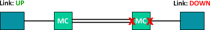
В примере выше, конечная точка с лева не может обнаружить выход из строя удаленного медиаконвертера, т.к. интерфейс подключенный к локальному медиаконвертеру остается в состоянии UP (Конечнко возможность появления такой ситуации зависит от медиаконвертора). UDLD способен обнаружить неисправность удаленного медиаконвертора путем констатации отсутствия UDLD сообщений от удаленного устройства.
По умолчанию, UDLD выключен на всех интерфейсах. Можно включить UDLD глобально на устройстве, или индивидуально на интерфейсе при помощи команды udld port. Это включит UDLD в режиме normal.
Может быть достаточно сложно скоординировать включение UDLD на обоих концах линии связи одновременно, в связи с этим при первом включении UDLD состоянии канала оценивается, как unknown,
что не означает состояние ошибки.
После включения UDLD на интерфейсе соседнего коммутатора, мы наблюдаем, что локальный коммутатор обнаружил соседнее устройство и изменил состояние канала на bidirectional.
UDLD способен отслеживать несколько соседних устройств на одном интерфейсе, но обычно этого не требуется.
Мы можем симулировать отказ канала и отследить реакцию UDLD. При использовании стандартных значений advertisement timer (15 секунд) и hold timer (5 секунд), реакция на проблему со стороны UDLD может занять до 20 секунд.
Как свидетельствует вывод команды debug представленный выше, с момента потери связи с соседним устройством, UDLD отправит сем дополнительных сообщений (по одному в секунду). И вслучае, если ответ не будет получен, статус канала (bidirectional status) станет равным unknown.
Естественно, это не очень большое преимущество т.к. интерфейс продолжает считаться действующим протоколами более высокого уровня и коммутатор продолжает отправлять трафик в этот канал. Как альтернатива режиму normal, можно настроить UDLD в aggressive режим. Режим аggressive отличается тем, что, в случае обнаружения односторонней связи на канале, интерфейс будет помещен в режим error-disabled и трафик перестанет передаваться. Такое состояние привлечет гораздо больше внимания администраторов к проблеме.
Перевод UDLD в режим aggressive, осуществляется добавлением аргумента aggressive к командам используемым ранее. Данный режим должен быть включен по обоим сторонам канала.
Можно убедится, что UDLD работает в режиме aggressive:
После очередной симуляции отказа,мы видим, что UDLD отвечает переводом канала в состояние error-disabled.
После устранения проблемы, можно вернуть интерфейс в рабочее состояние либо при помощи shutdown, no shutdown либо используя команду udld reset, которая автоматически восстановит работоспособность интерфейсов переведенных в состояние error-disabled в результате работы UDLD.
Udld cisco что это
This chapter describes how to configure the UniDirectional Link Detection (UDLD) protocol in Cisco IOS Software Release 12.2SX.

Note ![]() For complete syntax and usage information for the commands used in this chapter, see the Cisco IOS Software Releases 12.2SX Command References at this URL:
For complete syntax and usage information for the commands used in this chapter, see the Cisco IOS Software Releases 12.2SX Command References at this URL:
This chapter consists of these sections:
•![]() Understanding UDLD
Understanding UDLD
•![]() Default UDLD Configuration
Default UDLD Configuration
•![]() Configuring UDLD
Configuring UDLD
Understanding UDLD
These sections describe how UDLD works:
•![]() UDLD Overview
UDLD Overview
•![]() UDLD Aggressive Mode
UDLD Aggressive Mode
UDLD Overview
The Cisco-proprietary UDLD protocol allows devices connected through fiber-optic or copper (for example, Category 5 cabling) Ethernet cables connected to LAN ports to monitor the physical configuration of the cables and detect when a unidirectional link exists. When a unidirectional link is detected, UDLD shuts down the affected LAN port and alerts the user. Unidirectional links can cause a variety of problems, including spanning tree topology loops.
UDLD is a Layer 2 protocol that works with the Layer 1 protocols to determine the physical status of a link. At Layer 1, autonegotiation takes care of physical signaling and fault detection. UDLD performs tasks that autonegotiation cannot perform, such as detecting the identities of neighbors and shutting down misconnected LAN ports. When you enable both autonegotiation and UDLD, Layer 1 and Layer 2 detections work together to prevent physical and logical unidirectional connections and the malfunctioning of other protocols.
A unidirectional link occurs whenever traffic transmitted by the local device over a link is received by the neighbor but traffic transmitted from the neighbor is not received by the local device. If one of the fiber strands in a pair is disconnected, as long as autonegotiation is active, the link does not stay up. In this case, the logical link is undetermined, and UDLD does not take any action. If both fibers are working normally at Layer 1, then UDLD at Layer 2 determines whether those fibers are connected correctly and whether traffic is flowing bidirectionally between the correct neighbors. This check cannot be performed by autonegotiation, because autonegotiation operates at Layer 1.
LAN ports with UDLD enabled periodically transmit UDLD packets to neighbor devices. If the packets are echoed back within a specific time frame and they are lacking a specific acknowledgment (echo), the link is flagged as unidirectional and the LAN port is shut down. Devices on both ends of the link must support UDLD in order for the protocol to successfully identify and disable unidirectional links.
Note ![]() By default, UDLD is locally disabled on copper LAN ports to avoid sending unnecessary control traffic on this type of media since it is often used for access ports.
By default, UDLD is locally disabled on copper LAN ports to avoid sending unnecessary control traffic on this type of media since it is often used for access ports.
Figure 9-1 shows an example of a unidirectional link condition. Switch B successfully receives traffic from Switch A on the port. However, Switch A does not receive traffic from Switch B on the same port. UDLD detects the problem and disables the port.
Figure 9-1 Unidirectional Link

UDLD Aggressive Mode
UDLD aggressive mode is disabled by default. Configure UDLD aggressive mode only on point-to-point links between network devices that support UDLD aggressive mode. With UDLD aggressive mode enabled, when a port on a bidirectional link that has a UDLD neighbor relationship established stops receiving UDLD packets, UDLD tries to reestablish the connection with the neighbor. After eight failed retries, the port is disabled.
To prevent spanning tree loops, nonaggressive UDLD with the default interval of 15 seconds is fast enough to shut down a unidirectional link before a blocking port transitions to the forwarding state (with default spanning tree parameters).
When you enable UDLD aggressive mode, you receive additional benefits in the following situations:
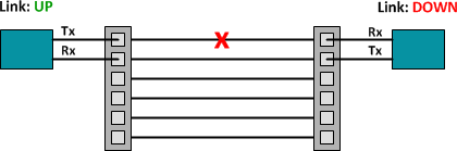
•![]() One side of a link has a port stuck (both Tx and Rx)
One side of a link has a port stuck (both Tx and Rx)
•![]() One side of a link remains up while the other side of the link has gone down
One side of a link remains up while the other side of the link has gone down
In these cases, UDLD aggressive mode disables one of the ports on the link, which prevents traffic from being discarding.
Default UDLD Configuration
Table 9-1 shows the default UDLD configuration.
Understand and Configure the UDLD Protocol Feature
Available Languages
Download Options
Contents
Introduction
This document explains how the Unidirectional Link Detection (UDLD) protocol can help to prevent forwarding loops and blackholing of traffic in switched networks.
Prerequisites
Requirements
There are no specific requirements for this document.
Components Used
This document is not restricted to specific software and hardware versions.
Conventions
Refer to Cisco Technical Tips Conventions for more information on document conventions.
Problem Definition
Spanning-Tree Protocol (STP) resolves redundant physical topology into a loop-free, tree-like forwarding topology.
This is done by blocking one or more ports. By blocking one or more ports, there are no loops in the forwarding topology. STP relies in its operation on reception and transmission of the Bridge Protocol Data Units (BPDUs). If the STP process that runs on the switch with a blocking port stops receiving BPDUs from its upstream (designated) switch on the port, STP eventually ages out the STP information for the port and moves it to the forwarding state. This creates a forwarding loop or STP loop.
Packets start to cycle indefinitely along the looped path, and consumes more and more bandwidth. This leads to a possible network outage.
How is it possible for the switch to stop receiving BPDUs while the port is up? The reason is unidirectional link. A link is considered unidirectional when this occurs:
The link is up on both sides of the connection. The local side is not receiving the packets sent by the remote side while remote side receives packets sent by local side.
Consider this scenario. The arrows indicate the flow of STP BPDUs.
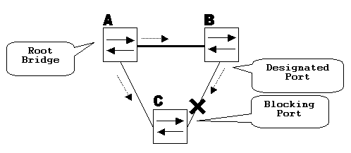
During normal operation, bridge B is designated on the link B-C. Bridge B sends BPDUs down to C, which is blocking the port. The port is blocked while C sees BPDUs from B on that link.
Now, consider what happens if the link B-C fails in the direction of C. C stops receiving traffic from B, however, B still receives traffic from C.
C stops receiving BPDUs on the link B-C, and ages the information received with the last BPDU. This takes up to 20 seconds, depending on the maxAge STP timer. Once the STP information is aged out on the port, that port transitions from the blocking state to the listening, learning, and eventually to the forwarding STP state. This creates a forwarding loop, as there is no blocking port in the triangle A-B-C. Packets cycle along the path (B still receives packets from C) taking additional bandwidth until the links are completely filled up. This brings the network down.

Another possible issue that can be caused by a unidirectional link is traffic blackholing.
How Unidirectional Link Detection Protocol Works
In order to detect the unidirectional links before the forwarding loop is created, Cisco designed and implemented the UDLD protocol.
UDLD is a Layer 2 (L2) protocol that works with the Layer 1 (L1) mechanisms to determine the physical status of a link. At Layer 1, auto-negotiation takes care of physical signaling and fault detection. UDLD performs tasks that auto-negotiation cannot perform, such as detecting the identities of neighbors and shutting down misconnected ports. When you enable both auto-negotiation and UDLD, Layer 1 and Layer 2 detections work together to prevent physical and logical unidirectional connections and the malfunctioning of other protocols.
UDLD works by exchanging protocol packets between the neighboring devices. In order for UDLD to work, both devices on the link must support UDLD and have it enabled on respective ports.
Each switch port configured for UDLD sends UDLD protocol packets that contain the port’s own device/port ID, and the neighbor’s device/port IDs seen by UDLD on that port. Neighboring ports should see their own device/port ID (echo) in the packets received from the other side.
If the port does not see its own device/port ID in the incoming UDLD packets for a specific duration of time, the link is considered unidirectional.
This echo-algorithm allows detection of these issues:
Link is up on both sides, however, packets are only received by one side.
Wiring mistakes when receive and transmit fibers are not connected to the same port on the remote side.
Once the unidirectional link is detected by UDLD, the respective port is disabled and this message is printed on the console:
UDLD-3-DISABLE: Unidirectional link detected on port 1/2. Port disabled
Port shutdown by UDLD remains disabled until it is manually reenabled, or until errdisable timeout expires (if configured).
UDLD Modes of Operation
UDLD can operate in two modes: normal and aggressive.
In normal mode, if the link state of the port was determined to be bi-directional and the UDLD information times out, no action is taken by UDLD. The port state for UDLD is marked as undetermined. The port behaves according to its STP state.
In aggressive mode, if the link state of the port is determined to be bi-directional and the UDLD information times out while the link on the port is still up, UDLD tries to re-establish the state of the port. If not successful, the port is put into the errdisable state.
Aging of UDLD information happens when the port that runs UDLD does not receive UDLD packets from the neighbor port for duration of hold time. The hold time for the port is dictated by the remote port and depends on the message interval at the remote side. The shorter the message interval, the shorter the hold time and the faster the detection. Recent implementations of UDLD allow configuration of message interval.
UDLD information can age out due to the high error rate on the port caused by some physical issue or duplex mismatch. Such packet drop does not mean that the link is unidirectional and UDLD in normal mode will not disable such link.
It is important to be able to choose the right message interval in order to ensure proper detection time. The message interval should be fast enough to detect the unidirectional link before the forwarding loop is created, however, it should not overload the switch CPU. The default message interval is 15 seconds, and is fast enough to detect the unidirectional link before the forwarding loop is created with default STP timers. The detection time is approximately equal to three times the message interval.
For example: Tdetection
This is 45 seconds for the default message interval of 15 seconds.
It takes Treconvergence=max_age + 2x forward_delay for the STP to reconverge in case of unidirectional link failure. With the default timers, it takes 20+2×15=50 seconds.
It is recommended to keep Tdetection module/port > command:
Issue this command to change the message interval:
The interval can range from 7 to 90 seconds, with the default being 15 seconds.
Refer to these documents for more information on the IOS UDLD configuration:
For Catalyst 6500/6000 switches that run Cisco IOS system software, refer to Configuring UDLD.
For Catalyst 2900XL/3500XL switches, refer to the Configuring UniDirectional Link Detection section of Configuring the Switch Ports.
For Catalyst 2940 switches, refer to Configuring UDLD.
For Catalyst 2950/2955 switches, refer to Configuring UDLD.
For Catalyst 2970 switches, refer to Configuring UDLD.
For Catalyst 3550 switches, refer to Configuring UDLD.
For Catalyst 3560 switches, refer to Configuring UDLD.
For Catalyst 4500/4000 running Cisco IOS, refer to Configuring UDLD.
STP в Cisco
Материал из Xgu.ru
 |
| Данная страница находится в разработке. Эта страница ещё не закончена. Информация, представленная здесь, может оказаться неполной или неверной. |
Если вы считаете, что её стоило бы доработать как можно быстрее, пожалуйста, скажите об этом.
На этой странице описывается процедура настройки различных версий протокола Spanning Tree на коммутаторах Cisco.
Содержание
[править] Петли в сети
Петли в коммутируемой сети могут возникнуть по нескольким причинам:
[править] Настройки по умолчанию
Настройки STP по умолчанию (для коммутатора 3550):
| Настройка | Значение по умолчанию | |||||||||||||||||||||||||||||||||||||||
|---|---|---|---|---|---|---|---|---|---|---|---|---|---|---|---|---|---|---|---|---|---|---|---|---|---|---|---|---|---|---|---|---|---|---|---|---|---|---|---|---|
| Состояние | Включен в VLAN 1 | |||||||||||||||||||||||||||||||||||||||
| Режим spanning-tree | PVST+ (Rapid PVST+ и MSTP выключены) | |||||||||||||||||||||||||||||||||||||||
| Приоритет коммутатора | 32768 | |||||||||||||||||||||||||||||||||||||||
| Приоритет портов (настраивается для каждого порта отдельно) | 128 | |||||||||||||||||||||||||||||||||||||||
| Стоимость порта (настраивается для каждого порта отдельно) | ||||||||||||||||||||||||||||||||||||||||
| Приоритет порта в VLAN (настраивается для каждого VLAN отдельно) | 128 | |||||||||||||||||||||||||||||||||||||||
| Стоимость порта в VLAN (настраивается для каждого VLAN отдельно) |
| Функция | Значение по умолчанию |
|---|---|
| Port Fast, BPDU filtering, BPDU guard | Глобально выключены |
| UplinkFast | Глобально выключена |
| Cross-Stack UplinkFast (CSUF) | Выключена на всех интерфейсах |
| BackboneFast | Глобально выключена |
| EtherChannel guard | Глобально включена |
| Root guard | Выключена на всех интерфейсах |
| Loop guard | Выключена на всех интерфейсах |
[править] Port Fast
Portfast — функция, которая позволяет порту пропустить состояния listening и learning и сразу же перейти в состояние forwarding. Настраивается на портах уровня доступа, к которым подключены пользователи или сервера.
Фактически, PortFast меняет две вещи в стандартной работе STP:
Когда на интерфейсе включен PortFast, он все равно отправляет BPDU.
Но, если включить PortFast на портах, которые соединены с другими коммутаторами, то есть риск создания петли. Так как, после получения BPDU порт остается в состоянии Forwarding. За это время, уже может образоваться петля.
Поэтому, в связке с PortFast, как правило, используется BPDUGuard (хотя и это, конечно же, не даст 100% гарантии, что не будет петли).
[править] Настройка Port Fast
Синтаксис команды для настройки Port Fast на интерфейсе:
Настройка Port Fast на access-интерфейсе:
Настройка Port Fast на интерфейсе, который работает в режиме trunk (тегированый порт):
Если на интерфейсе, который работает в режиме транка выполнить команду без параметра trunk, то функция Port Fast не будет применена.
Функцию Port Fast можно настроить глобально на всех интерфейсах в режиме access:
Отключить Port Fast на интерфейсе:
[править] Просмотр информации о настройках Port Fast
Просмотр информации о статусе функции Port Fast на интерфейсе:
Просмотр информации о настройках spanning-tree на интерфейсе:
Если Port Fast была включена глобально на всех access-портах, то это можно посмотреть в суммарной информации о настройках STP на коммутаторе:
[править] UplinkFast
Проприетарное усовершенствование протокола 802.1D сделанное Cisco. В RSTP эта функция не используются, так как улучшения уже встроены в протокол.
После включения UplinkFast на коммутаторе:
Если основной RP выходит из строя, то коммутатор сразу переключается на запасной и переводит его в состояние forward.
Кроме того, UplinkFast позволяет коммутаторам обновить записи в таблицах коммутации, без использования TCN. Вместо TCN коммутатор находит MAC-адреса всех локальных устройств и отправляет один multicast фрейм с каждым MAC-адресом в поле отправитель. Удаляются также остальные записи в таблицы коммутации самого коммутатора.
[править] BackboneFast
Проприетарное усовершенствование протокола 802.1D сделанное Cisco. В RSTP эта функция не используются, так как улучшения уже встроены в протокол.
Позволяет быстрее найти альтернативный путь, после изменения топологии. Для того чтобы функция работала, необходимо включить её на всех коммутаторах в сети.
[править] Безопасность STP
[править] BPDU Guard
BPDU Guard — функция, которая позволяет выключать порт при получении BPDU.
Может быть включена глобально на коммутаторе или на интерфейсе, у этих режимов есть некоторые отличия:
[править] Настройка BPDU Guard
Включение BPDU Guard глобально на коммутаторе, на портах с включенной функцией Port Fast:
Хотя в команде, которая включает BPDU Guard глобально на коммутаторе, есть параметр portfast, применение этой команды не включает функцию Port Fast. Она должна быть настроена отдельно.
Настройка BPDU Guard на интерфейсе:
[править] Просмотр информации о настройках BPDU Guard
Просмотр информации о настройках spanning-tree на интерфейсе:
Если функция BPDU Guard была включена глобально на коммутаторе, то это можно посмотреть в суммарной информации о настройках STP на коммутаторе:
[править] BPDU Filtering
BPDU Filtering — после включения функции, порт не принимает и не отправляет BPDU.
Может быть включена глобально на коммутаторе или на интерфейсе, у этих режимов есть некоторые отличия:
Возможные комбинации при включении BPDU Filtering глобально или на интерфейсе:
| Настройка на интерфейсе | Глобальная настройка | Состояние PortFast | Состояние PortFast BPDU Filtering |
|---|---|---|---|
| По умолчанию | Включена | Включена | Включена |
| По умолчанию | Включена | Отключена | Отключена |
| По умолчанию | Отключена | Не применимо | Отключена |
| Отключена | Не применимо | Не применимо | Отключена |
| Включена | Не применимо | Не применимо | Включена |
[править] Настройка BPDU Filtering
Включение BPDU Filtering глобально на коммутаторе, на портах с включенной функцией Port Fast:
Хотя в команде, которая включает BPDU Filtering глобально на коммутаторе, есть параметр portfast, применение этой команды не включает функцию Port Fast. Она должна быть настроена отдельно.
Настройка BPDU Filtering на интерфейсе:
[править] Просмотр информации о настройках BPDU Filtering
Просмотр информации о настройках spanning-tree на интерфейсе:
Если функция BPDU Filtering была включена глобально на коммутаторе, то это можно посмотреть в суммарной информации о настройках STP на коммутаторе:
[править] Root Guard
Включение Root Guard на интерфейсе (переводит порт в роль designated):
Посмотреть какие порты в состоянии inconsistent:
[править] Loop Guard
Одна из проблем с STP в том, что само оборудование, которое его использует, может быть причиной сбоя и создания петли. Для предотвращения подобных сбоев и была создана функция Loop Guard.
Описание Loop Guard
Как только на порт снова начинают поступать BPDU порт переводится в состояние согласно содержанию пакетов BPDU, а в логах появится следующее сообщение:
На каких портах следует включать Loop Guard? Наиболее очевидный ответ blocking. Однако это не всегда правильно. Loop guard должен быть включен на non-designated портах (более точно root и alternate портах).
По умолчанию Loop guard выключен. Для того что бы его включить используйте следующие команды:
Что бы включить Loop guard глобально:
Команда для проверки статуса Loop Guard:
[править] UDLD
[править] Совместимость и отличия функций
[править] Loop Guard в сравнении с UDLD
Функции Loop Guard и UDLD (Unidirectional Link Detection) частично совпадают друг с другом. Обе эти функции предназначены для борьбы с последствиями сбоев в функциональности STP. Однако есть небольшие отличия в функциональности.