Catalyst 6500 Release 12.2SY Software Configuration Guide
Book Title
Catalyst 6500 Release 12.2SY Software Configuration Guide
Chapter Title
Stateful Switchover (SSO)
View with Adobe Reader on a variety of devices
Results
Chapter: Stateful Switchover (SSO)
Stateful Switchover (SSO)
Note ● ![]() For complete syntax and usage information for the commands used in this chapter, see these publications:
For complete syntax and usage information for the commands used in this chapter, see these publications:
Tip For additional information about Cisco Catalyst 6500 Series Switches (including configuration examples and troubleshooting information), see the documents listed on this page:
Prerequisites for SSO
Restrictions for SSO
General Restrictions
Configuration Mode Restrictions
Switchover Process Restrictions
Information About SSO
SSO Overview
The switch is supports fault resistance by allowing a redundant supervisor engine to take over if the primary supervisor engine fails. Cisco SSO (frequently used with NSF) minimizes the time a network is unavailable to its users following a switchover while continuing to forward IP packets. The switch is supports route processor redundancy (RPR). For more information, see Chapter8, “Route Processor Redundancy (RPR)”
SSO is particularly useful at the network edge. Traditionally, core routers protect against network faults using router redundancy and mesh connections that allow traffic to bypass failed network elements. SSO provides protection for network edge devices with dual Route Processors (RPs) that represent a single point of failure in the network design, and where an outage might result in loss of service for customers.
SSO has many benefits. Because the SSO feature maintains stateful feature information, user session information is maintained during a switchover, and line cards continue to forward network traffic with no loss of sessions, providing improved network availability. SSO provides a faster switchover than RPR by fully initializing and fully configuring the standby RP, and by synchronizing state information, which can reduce the time required for routing protocols to converge. Network stability may be improved with the reduction in the number of route flaps had been created when routers in the network failed and lost their routing tables.
SSO is required by the Cisco Nonstop Forwarding (NSF) feature (see Chapter 7, “Nonstop Forwarding (NSF)”).
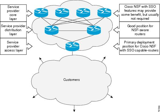
Figure 6-1 illustrates how SSO is typically deployed in service provider networks. In this example, Cisco NSF with SSO is primarily at the access layer (edge) of the service provider network. A fault at this point could result in loss of service for enterprise customers requiring access to the service provider network.
For Cisco NSF protocols that require neighboring devices to participate in Cisco NSF, Cisco NSF-aware software images must be installed on those neighboring distribution layer devices. Additional network availability benefits might be achieved by applying Cisco NSF and SSO features at the core layer of your network; however, consult your network design engineers to evaluate your specific site requirements.
Figure 6-1 Cisco NSF with SSO Network Deployment: Service Provider Networks
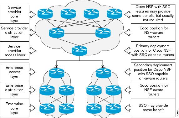
Additional levels of availability may be gained by deploying Cisco NSF with SSO at other points in the network where a single point of failure exists. Figure 6-2 illustrates an optional deployment strategy that applies Cisco NSF with SSO at the enterprise network access layer. In this example, each access point in the enterprise network represents another single point of failure in the network design. In the event of a switchover or a planned software upgrade, enterprise customer sessions would continue uninterrupted through the network.
Figure 6-2 Cisco NSF with SSO Network Deployment: Enterprise Networks
SSO Operation
SSO establishes one of the RPs as the active processor while the other RP is designated as the standby processor. SSO fully initializes the standby RP, and then synchronizes critical state information between the active and standby RP.
During an SSO switchover, the line cards are not reset, which provides faster switchover between the processors. The following events cause a switchover:
An SSO switchover does not interrupt Layer 2 traffic. An SSO switchover preserves FIB and adjacency entries and can forward Layer 3 traffic after a switchover. SSO switchover duration is between 0 and 3 seconds.
Route Processor Synchronization
Synchronization Overview
In networking devices running SSO, both RPs must be running the same configuration so that the standby RP is always ready to assume control if the active RP fails. SSO synchronizes the configuration information from the active RP to the standby RP at startup and whenever changes to the active RP configuration occur. This synchronization occurs in two separate phases:
Bulk Synchronization During Initialization
When a system with SSO is initialized, the active RP performs a chassis discovery (discovery of the number and type of line cards and fabric cards, if available, in the system) and parses the startup configuration file.
The active RP then synchronizes this data to the standby RP and instructs the standby RP to complete its initialization. This method ensures that both RPs contain the same configuration information.
Even though the standby RP is fully initialized, it interacts only with the active RP to receive incremental changes to the configuration files as they occur. Executing CLI commands on the standby RP is not supported.
Synchronization of Startup Configuration
During system startup, the startup configuration file is copied from the active RP to the standby RP. Any existing startup configuration file on the standby RP is overwritten.
The startup configuration is a text file stored in the NVRAM of the RP. It is synchronized whenever you perform the following operations:
Incremental Synchronization
Incremental Synchronization Overview
After both RPs are fully initialized, any further changes to the running configuration or active RP states are synchronized to the standby RP as they occur. Active RP states are updated as a result of processing feature information, external events (such as the interface becoming up or down), or user configuration commands (using CLI commands or Simple Network Management Protocol [SNMP]) or other internal events.
CLI Commands
CLI changes to the running configuration are synchronized from the active RP to the standby RP. In effect, the CLI command is run on both the active and the standby RP.
SNMP SET Commands
Configuration changes caused by an SNMP set operation are synchronized on a case-by-case basis. Currently only two SNMP configuration set operations are supported:
Routing and Forwarding Information
Routing and forwarding information is synchronized to the standby RP:
Chassis State
Changes to the chassis state due to line card insertion or removal are synchronized to the standby RP.
Line Card State
Changes to the line card states are synchronized to the standby RP. Line card state information is initially obtained during bulk synchronization of the standby RP. Following bulk synchronization, line card events, such as whether the interface is up or down, received at the active processor are synchronized to the standby RP.
Counters and Statistics
The various counters and statistics maintained in the active RP are not synchronized because they may change often and because the degree of synchronization they require is substantial. The volume of information associated with statistics makes synchronizing them impractical.

Note ![]() Not synchronizing counters and statistics between RPs may create problems for external network management systems that monitor this information.
Not synchronizing counters and statistics between RPs may create problems for external network management systems that monitor this information.
SSO Operation
SSO Conditions
An automatic or manual switchover may occur under the following conditions:
The user can force the switchover from the active RP to the standby RP by using a CLI command. This manual procedure allows for a “graceful” or controlled shutdown of the active RP and switchover to the standby RP. This graceful shutdown allows critical cleanup to occur.
Note ![]() This procedure should not be confused with the graceful shutdown procedure for routing protocols in core routers—they are separate mechanisms.
This procedure should not be confused with the graceful shutdown procedure for routing protocols in core routers—they are separate mechanisms.
 Caution
 ![]() The SSO feature introduces a number of new command and command changes, including commands to manually cause a switchover. The reload command does not cause a switchover. The reload command causes a full reload of the box, removing all table entries, resetting all line cards, and interrupting nonstop forwarding.
The SSO feature introduces a number of new command and command changes, including commands to manually cause a switchover. The reload command does not cause a switchover. The reload command causes a full reload of the box, removing all table entries, resetting all line cards, and interrupting nonstop forwarding.
Switchover Time
The time required by the device to switch over from the active RP to the standby RP is between zero and three seconds.
Although the newly active processor takes over almost immediately following a switchover, the time required for the device to begin operating again in full redundancy (SSO) mode can be several minutes, depending on the platform. The length of time can be due to a number of factors including the time needed for the previously active processor to obtain crash information, load code and microcode, and synchronize configurations between processors.
On DFC-equipped switching modules, forwarding information is distributed, and packets forwarded from the same line card should have little to no forwarding delay; however, forwarding packets between line cards requires interaction with the RP, meaning that packet forwarding might have to wait for the switchover time.
Online Removal of the Active RP
Online removal of the active RP automatically forces a stateful switchover to the standby RP.
Fast Software Upgrade
You can use Fast Software Upgrade (FSU) to reduce planned downtime. With FSU, you can configure the system to switch over to a standby RP that is preloaded with an upgraded Cisco IOS software image. FSU reduces outage time during a software upgrade by transferring functions to the standby RP that has the upgraded Cisco IOS software preinstalled. You can also use FSU to downgrade a system to an older version of Cisco OS or have a backup system loaded for downgrading to a previous image immediately after an upgrade.
SSO must be configured on the networking device before performing FSU.
Note ![]() During the upgrade process, different images will be loaded on the RPs for a short period of time. During this time, the device will operate in RPR mode.
During the upgrade process, different images will be loaded on the RPs for a short period of time. During this time, the device will operate in RPR mode.
Core Dump Operation
In networking devices that support SSO, the newly active primary processor runs the core dump operation after the switchover has taken place. Not having to wait for dump operations effectively decreases the switchover time between processors.
Following the switchover, the newly active RP will wait for a period of time for the core dump to complete before attempting to reload the formerly active RP. The time period is configurable. For example, on some platforms an hour or more may be required for the formerly active RP to perform a coredump, and it might not be site policy to wait that much time before resetting and reloading the formerly active RP. In the event that the core dump does not complete within the time period provided, the standby is reset and reloaded regardless of whether it is still performing a core dump.
The core dump process adds the slot number to the core dump file to identify which processor generated the file content.
Note ![]() Core dumps are generally useful only to your technical support representative. The core dump file, which is a very large binary file, must be transferred using the TFTP, FTP, or remote copy protocol (rcp) server and subsequently interpreted by a Cisco Technical Assistance Center (TAC) representative that has access to source code and detailed memory maps.
Core dumps are generally useful only to your technical support representative. The core dump file, which is a very large binary file, must be transferred using the TFTP, FTP, or remote copy protocol (rcp) server and subsequently interpreted by a Cisco Technical Assistance Center (TAC) representative that has access to source code and detailed memory maps.
SSO-Aware Features
A feature is SSO-aware if it maintains, either partially or completely, undisturbed operation through an RP switchover. State information for SSO-aware features is synchronized from active to standby to achieve stateful switchover for those features.
The dynamically created state of SSO-unaware features is lost on switchover and must be reinitialized and restarted on switchover.
The output of the show redundancy clients command displays the SSO-aware features (see the “Verifying SSO Features” section).
Default Settings for SSO
How to Configure SSO
Note ![]() See “Fast Software Upgrade,” for information about how to copy images onto the switch. During the upgrade process, different images will be loaded on the RPs for a very short period of time. If a switchover occurs during this time, the device will recover in RPR mode.
See “Fast Software Upgrade,” for information about how to copy images onto the switch. During the upgrade process, different images will be loaded on the RPs for a very short period of time. If a switchover occurs during this time, the device will recover in RPR mode.
Either the SSO or RPR redundancy mode is always configured. The SSO redundancy mode is configured by default. To revert to the default SSO redundancy mode from the RPR redundancy mode, perform this task:
Enables privileged EXEC mode (enter your password if prompted).
Router# configure terminal
Enters global configuration mode.
Enters redundancy configuration mode.
Router(config)# mode sso
Sets the redundancy configuration mode to SSO on both the active and standby RP.
Note After configuring SSO mode, the standby RP will automatically reset.
Exits redundancy configuration mode and returns the switch to privileged EXEC mode.
Router# copy running-config startup-config
Saves the configuration changes to the startup configuration file.
This example shows how to configure the SSO redundancy mode:
Router> enable Router# configure terminal Router(config)# redundancy Router(config)# mode sso Router(config-red)# end Router# copy running-config startup-config Router#
Troubleshooting SSO
Possible SSO Problem Situations
For example, during the upgrade process different images will be loaded on the RPs for a short period of time. If a switchover occurs during this time, the device will recover in RPR mode.
This is normal behavior. Until the FSU procedure is complete, each RP will be running a different software version. While the RPs are running different software versions, the mode will change to either RPR. The device will change to SSO mode once the upgrade has completed.
In Cisco IOS software, you can enter ROM monitor mode by restarting the switch and then pressing the Break key or issuing a “send break” command from a telnet session during the first 60 seconds of startup.The send break function can be useful for experienced users or for users under the direction of a Cisco Technical Assistance Center (TAC) representative to recover from certain system problems or to evaluate the cause of system problems.
SSO Troubleshooting
The following commands may be used as needed to troubleshoot the SSO feature. These commands do not have to be entered in any particular order.
Router(config-red)# crashdump-timeout [ mm | hh : mm ]
Sets the longest time that the newly active RP will wait before reloading the formerly active RP.
Router# debug redundancy < all| ui | clk | hub >
Debugs redundancy on the networking device.
Router# show diag [ slot-number | chassis | subslot slot / subslot ] [ details | summary ]
Displays hardware information.
Router# show redundancy [ clients | counters | debug-log | handover | history | switchover history | states | inter-device ]
Displays the redundancy configuration mode of the RP. Also displays information about the number of switchovers, system uptime, processor uptime, and redundancy state, and reasons for any switchovers.
Router# show version
Displays image information for each RP.
Verifying the SSO Configuration
Verifying that SSO Is Configured
In the following example, the show redundancy command is used to verify that SSO is configured on the device.
Verifying that SSO Is Operating on the Device
In the following example, the show redundancy command with the states keyword is used to verify that SSO is configured on the device.
Verifying SSO Features
Enter the show redundancy clients command to display the list of features that have registered as SSO features.
Router# show redundancy clients clientID = 0 clientSeq = 0 RF_INTERNAL_MSG clientID = 1319 clientSeq = 1 Cat6k Platform First clientID = 29 clientSeq = 60 Redundancy Mode RF clientID = 139 clientSeq = 61 IfIndex clientID = 3300 clientSeq = 62 Persistent Variable clientID = 25 clientSeq = 68 CHKPT RF clientID = 1515 clientSeq = 69 HAL RF clientID = 3100 clientSeq = 73 MCM clientID = 77 clientSeq = 80 Event Manager clientID = 1328 clientSeq = 81 Cat6k Asic API RF Cl clientID = 1334 clientSeq = 82 Cat6k AUTOSHUT RF Cl clientID = 1333 clientSeq = 83 Cat6k OVERSUB RF Cli clientID = 1302 clientSeq = 84 Cat6k Fabric Manager clientID = 1331 clientSeq = 86 Cat6k Inline Power clientID = 1303 clientSeq = 88 Cat6k OIR clientID = 518 clientSeq = 89 PM Port Data clientID = 1306 clientSeq = 93 Cat6k QoS Manager clientID = 1501 clientSeq = 98 Cat6k CWAN HA clientID = 1503 clientSeq = 99 CWAN VLAN RF Client clientID = 1310 clientSeq = 100 Cat6k Feature Manage clientID = 1700 clientSeq = 101 Cat6k L3 Lif clientID = 78 clientSeq = 102 TSPTUN HA clientID = 305 clientSeq = 103 Multicast ISSU Conso clientID = 304 clientSeq = 104 IP multicast RF Clie clientID = 22 clientSeq = 105 Network RF Client clientID = 88 clientSeq = 106 HSRP clientID = 114 clientSeq = 107 GLBP clientID = 225 clientSeq = 108 VRRP clientID = 1505 clientSeq = 111 Cat6k SPA TSM clientID = 1509 clientSeq = 114 Cat6k Online Diag HA clientID = 1337 clientSeq = 116 Cat6k MPLS RF Client clientID = 75 clientSeq = 120 Tableid HA clientID = 1338 clientSeq = 124 Cat6k CTS Manager clientID = 512 clientSeq = 126 LAN-Switch BD Manage clientID = 501 clientSeq = 127 LAN-Switch VTP VLAN clientID = 513 clientSeq = 128 LAN-Switch IDBHAL clientID = 71 clientSeq = 129 XDR RRP RF Client clientID = 24 clientSeq = 130 CEF RRP RF Client clientID = 146 clientSeq = 132 BFD RF Client clientID = 301 clientSeq = 135 MRIB RP RF Client clientID = 306 clientSeq = 139 MFIB RRP RF Client clientID = 1504 clientSeq = 146 Cat6k CWAN Interface clientID = 1507 clientSeq = 147 CWAN LTL Mgr HA RF C clientID = 520 clientSeq = 151 RFS RF clientID = 210 clientSeq = 152 Auth Mgr clientID = 5 clientSeq = 153 Config Sync RF clien clientID = 138 clientSeq = 155 MDR SM clientID = 1308 clientSeq = 156 Cat6k Local Target L clientID = 1351 clientSeq = 157 RF VS Client clientID = 1358 clientSeq = 158 Cat6k VSlot clientID = 502 clientSeq = 162 LAN-Switch Port Mana clientID = 514 clientSeq = 163 SWITCH_VLAN_HA clientID = 1313 clientSeq = 165 Cat6k Platform clientID = 1318 clientSeq = 166 Cat6k Power clientID = 23 clientSeq = 171 Frame Relay clientID = 49 clientSeq = 172 HDLC clientID = 72 clientSeq = 173 LSD HA Proc clientID = 113 clientSeq = 174 MFI STATIC HA Proc clientID = 1335 clientSeq = 180 C6K EFP RF client clientID = 200 clientSeq = 181 ETHERNET OAM RF clientID = 207 clientSeq = 183 ECFM RF clientID = 202 clientSeq = 184 ETHERNET LMI RF clientID = 208 clientSeq = 186 LLDP clientID = 20 clientSeq = 193 IPROUTING NSF RF cli clientID = 21 clientSeq = 197 PPP RF clientID = 1352 clientSeq = 201 C6K_provision_rf_cli clientID = 1307 clientSeq = 202 Cat6k IDPROM clientID = 74 clientSeq = 206 MPLS VPN HA Client clientID = 34 clientSeq = 208 SNMP RF Client clientID = 1502 clientSeq = 209 CWAN APS HA RF Clien clientID = 52 clientSeq = 210 ATM clientID = 35 clientSeq = 219 History RF Client clientID = 90 clientSeq = 231 RSVP HA Services clientID = 250 clientSeq = 243 EEM Server RF CLIENT clientID = 252 clientSeq = 245 EEM POLICY-DIR RF CL clientID = 54 clientSeq = 247 SNMP HA RF Client clientID = 73 clientSeq = 248 LDP HA clientID = 76 clientSeq = 249 IPRM clientID = 57 clientSeq = 250 ARP clientID = 50 clientSeq = 257 FH_RF_Event_Detector clientID = 1508 clientSeq = 263 CWAN LTL SP RF Clien clientID = 1304 clientSeq = 267 Cat6k Ehc clientID = 1305 clientSeq = 271 Cat6k PAgP/LACP clientID = 503 clientSeq = 272 Spanning-Tree Protoc clientID = 1309 clientSeq = 273 CMRP RF Client clientID = 1311 clientSeq = 275 Cat6k L3 Manager clientID = 1317 clientSeq = 276 Cat6k CAPI clientID = 1506 clientSeq = 277 CWAN SRP RF Client clientID = 83 clientSeq = 284 AC RF Client clientID = 145 clientSeq = 285 VFI Mgr clientID = 84 clientSeq = 286 AToM manager clientID = 85 clientSeq = 287 SSM clientID = 87 clientSeq = 291 SLB RF Client clientID = 504 clientSeq = 294 Switch SPAN client clientID = 507 clientSeq = 295 Switch Backup Interf clientID = 105 clientSeq = 298 DHCP Snooping clientID = 1510 clientSeq = 304 Call-Home RF clientID = 203 clientSeq = 307 MVRP RF clientID = 151 clientSeq = 310 IP Tunnel RF clientID = 94 clientSeq = 311 Config Verify RF cli clientID = 516 clientSeq = 314 EnergyWise rf client clientID = 508 clientSeq = 316 Port Security Client clientID = 509 clientSeq = 317 LAN-Switch IP Host T clientID = 515 clientSeq = 318 SISF table clientID = 135 clientSeq = 322 IKE RF Client clientID = 136 clientSeq = 323 IPSEC RF Client clientID = 130 clientSeq = 324 CRYPTO RSA clientID = 400 clientSeq = 326 IP Admission RF Clie clientID = 3099 clientSeq = 335 ISSU process clientID = 4005 clientSeq = 338 ISSU Test Client clientID = 93 clientSeq = 342 Network RF 2 Client clientID = 1320 clientSeq = 343 Cat6k PF_ML_RP clientID = 510 clientSeq = 345 LAN-Switch PAgP/LACP clientID = 511 clientSeq = 346 LAN-Switch Private V clientID = 1321 clientSeq = 347 PM SP client clientID = 1322 clientSeq = 348 VLAN Mapping clientID = 1315 clientSeq = 350 Cat6k Clear Counter clientID = 141 clientSeq = 352 DATA DESCRIPTOR RF C clientID = 1000 clientSeq = 361 CTS HA clientID = 1001 clientSeq = 362 Keystore clientID = 3150 clientSeq = 363 SIA SD RF CLIENT clientID = 3151 clientSeq = 364 SIA SB RF CLIENT clientID = 3152 clientSeq = 365 SIA SCL RF CLIENT clientID = 3153 clientSeq = 366 SIA SVE RF CLIENT clientID = 3154 clientSeq = 367 SIA TCP RF CLIENT clientID = 1332 clientSeq = 373 PCLC clientID = 1367 clientSeq = 375 Cat6k ITASCA_RP clientID = 4032 clientSeq = 379 ACL handle RF Client clientID = 4020 clientSeq = 381 IOS Config ARCHIVE clientID = 4021 clientSeq = 382 IOS Config ROLLBACK clientID = 1339 clientSeq = 404 Cat6k blue beacon RF clientID = 1362 clientSeq = 405 VS HA clientID = 517 clientSeq = 406 LAN-Switch IDBHAL2 clientID = 1336 clientSeq = 415 Cat6k NTI SUP SI swi clientID = 65000 clientSeq = 416 RF_LAST_CLIENT
Configuration Examples for SSO
This example configures the SSO redundancy mode :
Router# configure terminal Router(config)# redundancy Router(config-red)# mode sso Router(config-red)# exit Router# copy running-config startup-config
Tip For additional information about Cisco Catalyst 6500 Series Switches (including configuration examples and troubleshooting information), see the documents listed on this page: